Expérience ICE – Instrument Champ Electrique
ICE Experiment
– Electric Field Instrument
1- Scientific Objectives.
The main objective of the
ICE experiment is to detect and characterize the electromagnetic perturbations
in the ionosphere that are associated with seismic activity. As a secondary
objective, this instrument also aims at characterizing the electromagnetic
effects that can be generated by tropospheric storms
in the ionosphere. In addition, it will provide real time observations that can
be of use for space weather purposes.
In
the last twenty years a number of papers have reported the detection of
electromagnetic signals related to earth's seismic activity. The corresponding
measurements cover a large range of frequencies, from ULF to HF, and were
obtained by ground-based instruments as well as from satellite probes. In many
cases, not only the understanding of the phenomena but also their proper
characterization has proven to be difficult due to the weakness of the signals,
the relative paucity of observations and hence their subsequent lack of meaningful
statistics and the difficulty of removing other natural signals that can mix
with, and indeed sometimes mask, those induced by seismic activity.
The
objective of the ICE instrument on DEMETER is thus to perform a continuous
survey of the DC and AC electric fields over a wide frequency range and with a
high sensitivity in order to search for possible electrostatic and/or
electromagnetic waves in the ionosphere that might be induced by seismic
activity. The instrument and the onboard data processing have been designed to
provide an optimum set of data in the various frequency ranges, emphasizing
full characterization of the 3 components of the waves at frequencies below 1
kHz and single axis waveform transmission and spectrum measurements at higher
frequencies.
2- Description of the experiment.
The
ICE experiment consists of 4 spherical sensors with embedded pre-amplifier
electronics mounted on the ends of 4 booms or antenna “arms” and associated electronics,
included in the BANT module, to fulfill the onboard signal processing requirements.
When measuring the potential difference between two of these sensors, ICE
operates as a double probe instrument in which the component of the electric
field is determined along the axis defined by the two sensors. Any pair of
sensors among the four can be used for this objective which enables the 3
components of the DC and AC vector electric field to be obtained. The
electronics encompasses an analog part with a set of filters and amplifiers to process
the analog signals from the sensors and a digital part to carry out the
waveform digitization, power spectra computation and telemetry interfaces.
Four
frequency ranges have been defined, DC / ULF [0-15 Hz], ELF [15
Hz-1 kHz], VLF [15 Hz-17.4 kHz] and HF [10 kHz-3.175 MHz]. Depending
on the frequency range and on the spacecraft and ICE modes of operation, the
data that are stored in the mass memory can be the waveform of the
signal obtained from either the voltage difference between two sensors or that
measured by a single sensor and the spacecraft potential, and/or the power
spectra of the signal obtained from the voltage difference between two
sensors. The data management scheme is described in more details in paragraph
2.2 below.
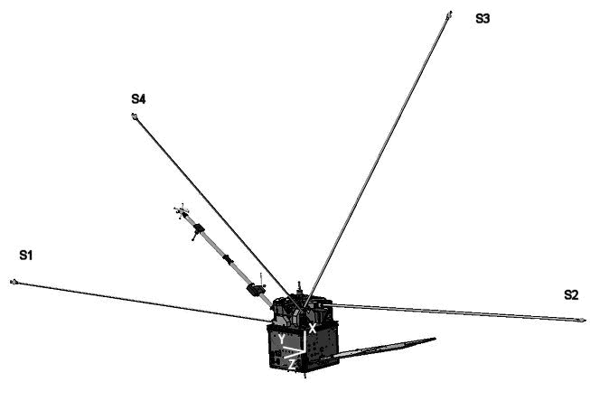
Figure
1: Position of the
ICE sensors on the spacecraft
2.1- Sensors.
The
4 sensors, labeled S1, S2, S3 and S4 in Figure 1, are spherical aluminum electrodes
60 mm in diameter each mounted at the end of a 4 meter deployable boom. With
such a length and the proper orientation of the booms as shown in Figure 1, the
sensors are kept at a sufficiently large distance of the spacecraft and its
wake which is induced by the motion of the spacecraft within the ionospheric plasma at meso-thermal
orbital velocities. Disturbances in the measurements that can arise from either
the extended plasma sheath or the wake of the spacecraft should therefore be
negligible under the plasma conditions that are expected along the orbit of
DEMETER. Due to the remote position of the sensors with respect to the
spacecraft body, electromagnetic interferences generated by the spacecraft
subsystems or other payload instruments are significantly reduced. Finally, the
orientation of the 4 booms have also been chosen so that the 3 components of
the electric fields that can be obtained from the voltage differences between
individual sensors, as indicated below, are close to a three axis orthogonal
configuration.
The
sensors are coated with a thin layer of carbon filled epoxy in order to
minimize the variations of the surface potential over the surface and improve
the quality of DC electric field measurements. The spherical shell of each
sensor includes a small electronics board consisting of a unity gain
preamplifier and a polarization current source. The current intensity, which is
the same for all 4 sensors, can be adjusted by telecommand
in order to keep the sensor sheath impedance to a sufficiently low value
irrespective of the varied plasma conditions that are anticipated along the
orbit. A low impedance is desirable to maintain
negligible phase shifts for the signals in the ELF range where the electric
field data are used to determine the wave propagation vector.
2.2- Data
management.
Signals
from the 4 sensors can be combined to provide 3 components of the electric
fields. The nominal configuration of these 3 components is the following:
-
E12 (≈ along the Y axis of the spacecraft) = S1-S2
-
E34 (≈ along the Z axis of the spacecraft) = S3-S4
- ER =
E13 = S1-S3
As seen
from above, the S1 and S3 sensors are used to measure 2 components of the
electric field vectors. In order to minimize the detrimental effects that might
arise should any of them fail, a telecommand
order is available to replace them by respectively S2 or S4 in the ER
component. Thus E12 and E34 are sent to telemetry irrespective of the sensors
status and the third component ER can be changed to E23 (=S2-S3) if S1 fails or
E14 (= S1-S4) if S3 fails.
The
onboard data processing and data storage in the mass memory depend on frequency
range and on the mode of operation of the spacecraft, Burst or Survey,
as well as, to a lesser extent, on the sub-mode of operation of the ICE
instrument.
2.2.1- DC and ULF
measurements.
In
both the Burst and Survey modes, signals from each of the 4 sensors, filtered
and amplified in a 0-15 Hz bandwidth, are digitized with 16 bits and stored in
the mass memory.
2.2.2- ELF
measurements.
The
3 ELF electric field components that will be used to derive the detailed
propagation characteristics of the electromagnetic waves are only available in
the Burst modes. They are filtered and amplified in a 15Hz-1kHz
bandwidth, digitized with 16 bits and stored in the mass memory.
2.2.3- VLF
measurements.
Only
one of the electric field components is processed. In the nominal configuration
this is the E12 component, but a telecommand order
allows one of the 2 other components, E34 or ER, to be selected.
The
electric field waveform is filtered and amplified in a 15Hz-17.4kHz
bandwidth and digitized with 16 bits. In addition, the power spectrum is
computed with frequency and temporal resolutions that depend on the spacecraft
and ICE modes of operation. Simultaneously, data are analyzed by a neural
network to detect the occurrence and characteristics of whistler emissions.
In
the Burst mode, both the waveform data and the power spectrum, with a 19.53 Hz
frequency resolution and averaged over 2.048 s, are stored in the mass memory.
In
the Survey modes, only the power spectrum is stored in the mass memory and
there are 3 ICE sub-modes. In the first one, labeled [0], the frequency and
temporal resolutions are identical to those of the Burst mode, in the second
one [1] the temporal resolution is increased to 0.512 s and in the third one
[3] the frequency resolution is decreased to 78.125 Hz by averaging over 4
consecutive frequencies.
2.2.4- HF measurements.
The
same electric field component used for the VLF range is processed in the HF
range. The waveform is filtered and amplified in the 10 kHz-3.175 MHz bandwidth
and digitized with 8 bit. The HF data acquisition is performed on 40 data
snapshots each 0.6144 ms long and evenly spaced in the 2.048 s elementary
interval of the VLF channel acquisition. Individual power spectra are
calculated for each snapshot with a frequency resolution of 3.25 kHz and
averaged to provide a power spectrum every 2.048 s.
In
the Burst mode, the average power spectrum and waveform data for a single
0.6144 ms interval are stored in the mass memory. The selected interval is
either the first of the 40 intervals or the one with the maximum total power
over the entire HF bandwidth.
In
the Survey modes, only power spectra information are stored and there are 3
sub-modes similar to those in the VLF Survey mode, with varied frequency and
temporal resolution: [0] and [1] provide a 3.25 kHz frequency resolution with
respectively a 2.048 s (average over 40 spectra) and 0.512 s (average over 10
spectra) temporal resolution while [2] provides a 13 kHz frequency resolution
(averaging over 4 consecutive frequencies) and 2.048 s temporal resolution.
3- Instrument
Performances
Figure
2 summarizes some preliminary calibration results showing the variation of the
ICE gain in the frequency range from DC to 3.125 MHz.
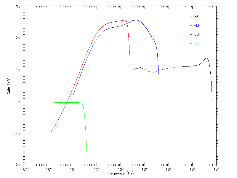
Figure 2: Frequency variation of the gain of the
electric field channels. In the ULF range the gain applies to the direct
measurement of the voltages of individual sensors. From ELF to HF, the
instrument provides a differential measurement between 2 sensors.