DEMETER-IDP
Recently, data from the low polar orbiting
satellites Intercosmos Bulgaria 1300 and Aureol-3
showed increases of the flux of electrons and ions with high energy (E> 100
keV) precipitating towards the ionosphere in correlation with an increases of
waves intensities at very low frequency (f < 1000 Hz). In several case,
these flux intensifications were associated with Earthquakesá (M>4) in
The measurement carried out by the micro-satellite DEMETER (Detection of electro-magnetic Emissions Transmitted from Earthquake Regions) have for goal to systematically study the electromagnetic waves observed at the time of earthquakes and volcano eruptions (and other phenomena, either natural or created by the human activity), the related ionospheric changes, and the precipitation of associated particles.á The scientific payload of the satellite is therefore composed from several types of sensors measuring waves and particles. This payload comprises the Instrument for Particle Detection- IDP, developed by the CESR that is intended for the measurement of the fluxes of energetic electrons in the energy range: 60 keV-600 keV.á The low polar orbit of the satellite (800 km altitude, heliosynchronous) and his life length of 2 years will allow it to survey frequently almost all the seismically active regions of the globe.á
Scientific objectives of IDP
During an interaction of a high energy particle from the EarthÆs radiation belt with a wave, the angle between the particle velocity vector and the magnetic field can be changed and the particle can thus reach the upper atmosphere where it precipitates.á One of the main scientific objectives of DEMETER-IDP consists to measure these modifications of the trajectories and energies of the particles by interaction with waves.á Particularly close to seismic epicenters.á A second objective is to understand the chain of physical processes leading to the observations before and after earthquakes.á Finally, a third objective is the systematic study of the radiation belt dynamics related to the changing interplanetary environment of the Earth.
Particle fluxes on a low altitude orbit
There are currently several numerical models describing the radiation belt flux content.á The NASA models AP8 and AE8, were used to carry out an estimation of the electron and ion fluxes along the DEMETER orbit. These models were elaborated from data taken since the sixties. Their output provide average particle fluxes in the radiation belts. Fluxes are omni-directionnal (integrated on 4p st‰radians). The average integral fluxes of electrons (E>40 keV) and of protons (E> 700 keV) at the DEMETER altitude are displayed in Figures 1 and 2.á
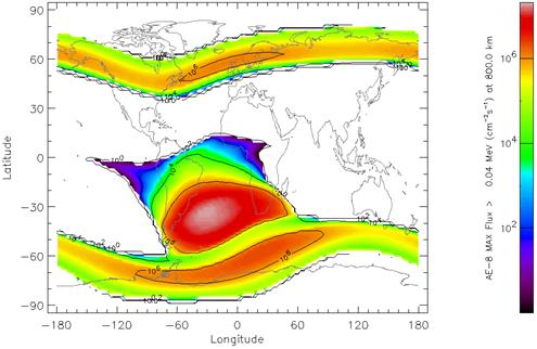
Figure 1: Integral fluxes of electrons with E > 40 keV at the DEMETER altitude

Figure 2: Integral fluxes of protons with E > 700 keV at the DEMETER altitude
Maximum fluxes are predicted just equatorward of the auroral zones (outer radiation belts)
and over the south Atlantic anomaly. Note that due to the displacement of the
Earth center and of the magnetic dipole center, the magnetic field is weaker
over the south
The IDP spectrometer
The IDP design was realized to allow the detection of very weak electron fluxes generally met on the DEMETER orbit outside the natural precipitation zones. In order to fulfill this requirement, the geometry factor of IDP is large ~ 1 cm™-sr.á The calculation of the geometry of the instrument and of the shielding thickness was performed for the complete energy range (i.e., from tens of keV up to the MeV range) using the GEANT-3 code from CERN.
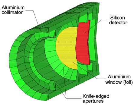
áFigure 3: Cross sectional view of IDP.á The collimator in Aluminum (green), the Al foil aimed to stop UV photons and protons with energies lower than 500 keV, and the Silicon detector (red
)

Figure 4: The sensor head
The sensor head comprises a collimator in Aluminium, light material particularly well adapted to minimize the bremsstrahlung.á The collimator is designed to provide a view angle of ˜ 30—.á And to stop a large number of secondary particles (electrons and photons) created on its the internal parts.á The optic has also an Aluminium foil with a thickness of 6 mmá to avoid all parasite light and to stop protons with E< 500 keV. Finally the Silicon detector is made of completely deserted silicon of 1 mm thickness. A photography of the detection head of IDP is given in Figure 4.á This sensor is located on a case that contains the associated electronics. Today the experiment is ready to flight.á
|
Detector |
Implanted Silicon Width :
1 mm Active surface 490 mm™ (Ë 25 mm) |
|
External shielding |
2 mm Al |
|
Foil for protons and
photons rejection |
6 mm Al |
|
Mass |
525 gr |
|
Power |
895 mW |
|
Energie range (e-) |
60 keV û ~ 600 keV, 256 channels |
Table
1 : Principal characteristics of IDP
Analogical and numerical Electronics
Figure 5 represents the sensor electronics. The signal coming from the Silicon diode is detected with a low-noise charge sensitive preamplifier. The total charge Q created by the passage of a ionizing radiation is converted to an electric impulse. Its height is proportional to the energy of the incident particle. In solid, and particularly in semi-conductors, the ionization of the medium shows itself by the transfer of electrons from the valence band to the conduction band. An electron-hole pair is created in the semiconductor. The total mean number of electron-hole pairs Ne-hole freed by the energy deposit DEdeposited is given by :á Ne-hole = DEdeposited/W, where W is the ionization energy. The freed electrons are then collected. The mean ionization energy, W, is always higher than the ionization potential, as a part of the energy of the incident particle excites the medium or is lost trough elastic nuclear collisions. For Silicon, W is about 3.6 eV, while the ionization potential is ~1.1 eV.

Figure 5: IDP block diagram
The amplitude of the collected impulse dV is proportional to the charge Q and therefore to the deposited energy. The impulse is amplified and shaped. But the length of the trailing edge of the impulse of several ms is incompatible with the need to be able to encode them with a repetition frequency reaching up to 0,5 MHz. áThe shaping circuit reduces the length of the impulses, and modifies them in order to allow a numerical encoding. Simultaneously, the analogical signals are applied to a low level threshold discriminator. The digitalization of the analogical signal is made by an ADC that carries out a linear analog to digital conversion of dV in 256 channels.

Figure 6: Acquisition card.
Numerisation, shaping
Calibrations
An incident electron penetrate inside the diode and there deposit up to 100% of its kinetic energy if it is stopped in the Silicon. The transfer matrix determines the relation between the incident energy of the particles and the deposited energy (Figure 7).á An electron beam widely distributed in energy has been launched uniformly on the entrance surface of the detector. At low energies, the deposited energy remains practically proportional to electron initial energy.á But at the highest energies, the simulation show different deposited energies. Nevertheless this effect is very limited in the energy range of IDP: from ~60 keV to 700 keV.á
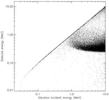
Figure 7: Measured energy as a
function of the energy of incident electrons (computations made with the code
GEANT-3/CERN)
Figure 8 show the spectral distribution of the energy deposited inside the detector by mono-energetic beams of electrons illuminating the whole entrance surface of the collimator.á At normal incidence. A fraction only of the deposited energy gives directly the incident energy of the electrons.á These curves are used to determine the efficiency of the detector.
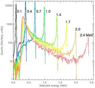
Figure 8: Distribution of the energy deposited inside theSilicin detector for wide incident mono-energetic beams.
Figure 9 gives the detector efficiency thus computed. 105 particles are launched for each energy on the collimator (diameter 2 cm).á
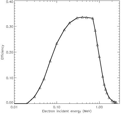
Figure 9: Detection efficiency of IDP
The detailed energy calibration of IDP were carried out with radioactive sources Cd109, Cs137 and Bi207 emitting electronic lines (by internal de-excitation of the nucleus) at 56.7, 62.5, 84.2, 87.3, 482.7, 553.8, 624.2, 655.7, 975.6, 1047.8 and 1059.8 keV, and X lines at 10.6, 22.0, 72.8, 75.0 and 84.9 keV. The particle energy loss in air was taken into account.
To calibrate the efficiency of the
detector, we used a Van of Graaff accelerator of
CERT/ONERA in

Figure 10: Integration of the detector on the satellite during the final tests
References:
Sauvaud, J.-A. et al., IDP-DEMETER, A proposal
to CNES, 1999
Cros, A., Dossier de contrŸle des interfaces, Document projet DEMETER, r‰f.
DMT-C1-7-DP-6702-CES3.2, 28 mai 2002
Moreau, T., Etude num‰rique de spectrometres embarquables de particules charg‰es, PhD,
Toulouse, March 3, 2003.
Coutelier, Jacques, Dossier de Mise au Point dÆIDP,
rapport CESR, 23 juin 2004